Bridge between the Terrestrial and the Beyond
- Theory and Practice of Transcommunication -
by Hildegard Schaefer (†)
13. Further variants
There exists a host of additional devices suitable for being arranged with or coupled to any wanted one of the several single methods; in some cases (pls. see item 2) they can also be employed alone.
1 Televisor
With each of the specified recording methods a televisor can additionally be switched on with the aim to augment and improve receipt. It will be preferable to choose a channel without program. Of course, it is also possible to switch on two televisors, like it is when working with two radio transmitters or two devices of any of the other equipment.
2
It is possible to do a recording using solely water rushing as a support. It is however more advantageous to join it to one of the other proved methods. The gurgling of water supplies an acoustic basic oscillation that has positive influence when endeavouring contact with “the other side”. It should be a low rushing or murmuring of water, say form a background, because too loud rushing causes noises-off that generate tones similar to voices, which can irritate very easily.
The combination of murmuring water and other additional aids mostly brings good results, but in view of the aforesaid, it is necessary to be critical when listening to the recorded.
When the room in which the recording is done has no water supply (hand-basin or similar equipment), a little electrically operated water-spout can be employed. These little fountains deliver an adjustable and uniform murmuring, and their price is moderate.
3 Tempting voice
Those experimenters having the voice of a dear deceased on a magnetic tape or a cassette may employ this original voice for recording, and further voiceless additional equipment may be added as well. There is quite a possibility that the person in the Beyond uses the material offered to him/her for formulating a message.
4 Infrared lamp
It is nothing new that red light has the capacity to promote the contact between this earthly world and the Beyond; already in the past red light has been used for non-technical contacts with an other dimension. Infrared and red light have an important part in those chapters in this book where I report on new recording methods.
5 Clocks or timers
Tick-tick clocks or watches placed near to the recorder are said to also provide further noises-off for improving contacts. A metronome or a similar time keeper may be used as well. A loud-ticking alarm-clock also fulfills the purpose of a timer. It is presumed that such a clock might serve for the adaptation of different time courses.
Timers are also used by the successful experimenters or groups presented in chapters following later (
6 Microphone amplifier
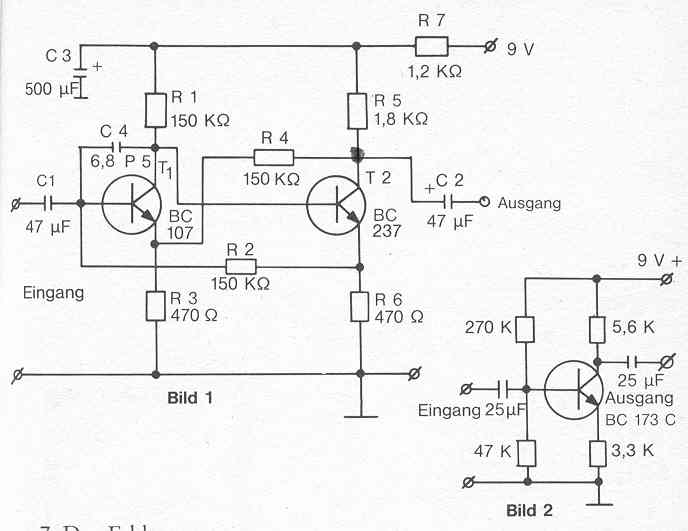
When doing microphone recordings it is recommendable to use a microphone amplifier to achieve optimum microphone performance. Several types of amplifiers are offered on the market. Here I describe the instrument recommended by Hans Otto Koenig, Moenchengladbach, and add its circuit diagram as published in the periodical Die Parastimme (the para-voice) in April 1986.
Since the receiver aerials determine almost exclusively the distance of noise voltage and external voltage of the entire amplifier, the switching must be designed especially free of noise and ripple. Therefore low-noise planar epitaxial transistors are used, and the supply voltage is carefully smoothened with additional filter sections. The working point of the very first amplification stage is chosen at that point where it gets minimum noise.
When in operation, dynamic microphones without transducer emit voltages of not more than approx. 0.5 mV to 2 mV with linear frequency response behaviour. Here the pre-amplifier’s task is only to lift the level. Circuit diagram 1 shows a two-stage microphone amplifier with directly coupled transistors. The basis bias of transistor T1 is dynamically generated by leading the emitter voltage of transistor T2 via resistor R2 to the basis of T1. Resistor R4, which effects reverse reaction, also serves to increase the dynamic level range. Capacitor C4 is positioned between the collector and the basis of transistor T1. With its low capacity value it builds an inverse reaction for high frequencies and thus avoids the occurrence of possible oscillation. This pre-amplifier switching does not comprise any other components influencing frequency response. Thus a transmission range of 4 Hz up to 40 Hz is obtained, which has positive effect on recordings. The amplification achieved amounts to 126. The maximum output voltage of 1.4 V is obtained with an input voltage of 11 mV. The switching being of optimum layout, a signal-to-hum ratio of more than 70dB is achieved. To keep hum noise low, the operating voltage is additionally filtered. Electret capacitor microphones feature a such high level that only little amplification is required. So it is possible to install a stronger negative follow-up into a two-stage amplifier, or to use a single-stage switching (acc. to diagram 2) only.

Translation: Eingang = input and Ausgang = output
7 The Feldgenerator (The field generator)
Our partners in the Beyond need a basis of oscillation to be able to make themselves acoustically understandable. Frequency fields are generated either by radio, by water or similar means. The energies of our partners in the Beyond have a frequency width of approx. 5 kHz which contains a field of dense oscillations of information. Hans Otto Koenig tried to offer his partners in the Beyond a similar synthetic field, this realized by the interfering of the two mentioned fields. The purpose is to get the information of our partners in the Beyond to within the range of audibility. The Feldgenerator generates itself a multi-frequency field, modifiable by manual levelling. It achieves a frequency width of 2.5 kHz up to 1700 kHz on an electro-magnetic oscillation basis. The system is of multi-vibrator type generating rectangular pulses. For recordings, the unit is employed as follows:
Actuate the ON/OFF lever (indicator lamp lights upon switch-on) to have the unit ready. Use the frequency regulator for trying to adjust the most advantageous form of oscillation for reaching the Beyond. It will have to be determined by doing several recordings. The Feldgenerator shall be placed at approx. 2 m to 3 m distance from the recorder (electromagnetic tape recorder or cassette recorder).
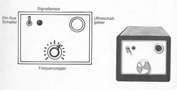
Feldgenerator:
diagram acc. to set-up drwg. of Hans Otto Koenig,
Translation:
Ein-Aus Schalter = ON/OFF switch
Ultraschall-geber = ultrasonic sound head
Signallampe = indicator lamp
Frequenzregler = frequency regulator
8 The Minigenerator
The Minigenerator is a small device of about the size of a lighter. On the market currently known as “midget scare-crow”, it has been modified in such manner that it emits oscillations which are outside our range of audibility and due to this offer a favourable basis of oscillation to our partners in the Beyond. These little devices are simply called “Piepser” (squeakers).
Since every single squeaker squeaks with a different frequency, say none of the devices is perfectly identical with an other like one, it is recommendable to place not only one but several squeakers differently spaced from the recording unit.
9 The parametric filter
This equipment serves to fade frequencies out or to raise them, which means to eliminate the noise field surrounding a paranormal voice to the best possible extent. The parametric filter is fitted with three regulators performing the following functions:
the first serves to select the frequency range,
the second to raise or lower the selected frequency, and
the third to determine the frequency band width or the focussing of a paranormal voice.
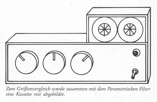
To illustrate the size, a cassette is shown together with the parametric filter
Description of the three regulators of the parametric filter :
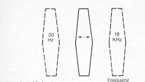 |
Button 1: Frequency selection As is recognizable on the sketch drawing, the frequency to be influenced is continuously adjustable across the entire LF range (audibility range) from 30 Hz to 18 kHz. With conventional tone control, the so-called operative frequencies are set fix. |
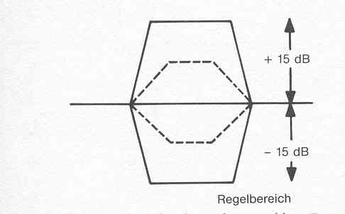 |
Button 2: Frequency raising or lowering are continuously adjustable as with every tone control. The setting range of +/- 15dB is independent from frequency adjustment or frequency quality. |
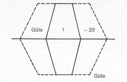 |
Button 3: It can be recognized from this parameter that - independently from the adjusted frequency - the band width can be continuously regulated between “quality 1 and quality 20” and due to this exercises differently strong influence on the changing of neighbouring frequencies. Consequently it is possible to raise or lower one certain frequency very “pointedly”, i.e., isolated, or to influence the neighbouring frequencies more or less as well. |
Remark on additional instruments
The additional equipment described under items 7, 8 and 9 have been developped and reconstructed, respectively, by an expert in transcommunication research. Later they were rebuilt by other technicians or amateurs either in their original form or with minor modifications.
(Via the publishing house you will receive from the author addresses for the acquisition of these units.)
|
You are visiting our website: W |