Psychophone II


Engineer Franz Seidl (+1982), (Austria) developed this device in the years 1972 to 1974 especially for EVP researches.

Three ways of receiving EVP could be performed:

a)

broadband reception of EM short -, middle- and long waves simultaneously

b)

self transmitting method
by adding an HF-oscillator (short wave range) and mixing this to the broadband reception signals in order to offer additional energy

c)

microphone method: a mike is connected to the Mikr. input and the signals will be mixed with the other signals

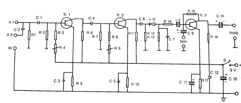
We show here the circuit diagram (taken from: "Bruecke zwischen Diesseits und Jenseits" - Hildegard Schaefer - 1989 - ISBN 3-7626-0374-X  and to be found on this website in the section "Books"):

Resistors 0,25 W:
R 1, R 2: 12 kOhm
R 3: 6 kOhm
R 4: regulator 0,1 MOhm
R 5: 390 Ohm
R 6: 820 Ohm
R 7: 12 kOhm
R 8: 6 kOhm
R 9: regulator 0,1 MOhm
R 10: 390 Ohm
R 11: 820 Ohm
R 12, R 13: 47 kOhm
R 14: 6 kOhm
R 15: 100 kOhm
R 16: 12 kOhm
R 17: 300 Ohm
Capacitors 16 V-:
C 1: 0,15 µF
C 2: 50 pF
C 3, 4, 5, 6, 12: 15 µF
C 7: 3 nF
C 8, 9, 10: 22 µF
C 11: 220 µF
C 13: 220 - 500 µF


Tr. 1, Tr. 2: like BF 310
Tr. 3:
like BC 413

HF diode:
AA 116, 1 N148


A 1, A 2: input antenna
M:
ground
Mikr.:
input microphone

Ausg.: output to recorder
S:
switch or R 9 as poti with switch

The Psychophone should be mounted in a shielded housing.

rodiehr 16 Jan 2003


 You are visiting our website:  Wrld ITC.org       To reach our homepage click here please.