click here to enlarge
S P I R I C O M
An Electromagnetic-Etheric Systems Approach to Communications
with other Levels of Human Consciousness
Page 42
CHAPTER 7
MARK V - A
210.25 GHz - 1977 and Continuing
Description and Theory of Operation
The purpose of this instrument is the testing and observation of interactions of spirit energies with electro-magnetic microwave energy in a more controlled manner than was possible with Mark II.
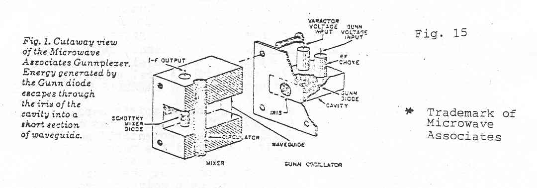
The instrument contains two Gunnplexers as a source of microwave energy. Their varactor- tuned- oscillators (VTO) operate at a normal frequency of 10.25 GHz (the receiving unit) and 10.28 GHz (the transmitter unit). Figure 15 shows a cutaway view of the Gunnplexer without antenna. The main components in the oscillator
cavity are the Gunn diode which will oscillate when supplied with 10 volts DC. Its output is approx . 15 - 25 microwave. A Varactor diode, when biased with a DC voltage (1 to 20 V) tunes the cavity over a span +/- 60 MHz. This is also the tuning range available at the I.F. tuning control on the front panel.
The cavity is coupled to a short waveguide that contains a very sensitive, low noise Schottky mixer diode. When the microwave energy generated by the Gunn oscillator escapes from the cavity and enters the waveguide, it passes by a ferrite rod circulator. The circulator samples a small amount of the signal and couples it to the Schottky diode. This mixer diode also furnishes the I.F. output for the instrument's amplifiers to be
described later.
The antenna connected to the waveguide serves as a transmission and reception antenna (gain -17 db) for each Gunnplexer. Similarly, each Gunnplexer unit is capable of sending and receiving but for the purposes of this set' the I.F. output of the transmitter is not used.
The interaction of the two oscillator signals produces two major "beat" frequencies in the Schottky diode: a sum and difference freq. The difference frequency of 0.03 GHz (or 30 MHz) also is the intermediate (I.F.) frequency of the associated amplifiers.
Page 43
We now had two carrier signals plus their sum frequency which together with their strong second harmonics should provide a broader area for spirit impingements. When the receiving unit is operated alone, spirit impingements ideally should be 30 MHz higher or lower than the 10.25 GHz carrier.
The receiving portion of Mark V consists of a low noise, high gain (90 dB) I. F. amplifier with its own AM detector. The I.F. output feeds into a Limiter/Discriminator which serves as a demodulator for frequency modulations (EM). The outputs of both units is available at the front panel. Both amplifiers are calibrated for 3 0 MHz I.F. at a bandwidth of 10 MHz. Thus audio and video observations are simultaneously possible.
Drift and Voltage Regulation
After a Gunnplexer is initially turned on, its output frequency drifts rapidly as the unit warms up. The typical drift rate is about 300 kHz per degree Celsius. The Gunnplexer temperature may go up to 10 degrees per minute after power is turned on, total frequency drift is 3 MHz or more. As the units reach thermal equilibrium, however, frequency drift slows and they will sit on frequency for hours at a time. To control drift and particularly to prevent the drifting a part of the two oscillators, their supply voltages have a common voltage regulator. Also the mounting of the Gunnplexers in the same enclosure assures the same rate of temperature-caused drift.
Tuning
The instrument allows a tuning range of at least 60 MHz for each oscillator. However, for practical reasons only the transmitter is tuneable on the front panel control marked "I.F. Tuning".
The front panel tuning meter provides an accurate means of tuning and zeroing to the center of the 30 MHz I.F. Freq. The tuning range is wide enough to observe also the I. F. "Image" frequencies. Switch on the 1 kHz test tone to aid in correct tuning and to help in the most efficient aiming of the horn antennas.
Page 44
On the possibility that one of the researchers who reads this material may want to build and experiment with this device or some modification thereof we present detailed information on this and the following page.
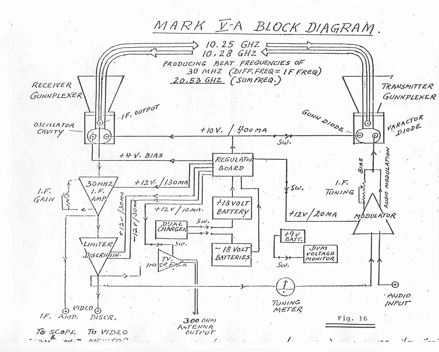
Fig. 16 : MARK V -A Block Diagram click here to enlarge
Page 45
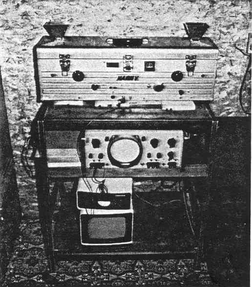
Fig. 17: MARK V
--------------------------------------------------------------------------------
Present Status (February 1982)
As of the time this first edition o f SPIRICOM goes to press, we report that with Mark V we have not been able to establish voice contact with our intended collaborators on the mental/causal level -- depicted in the large diagram, "IN OUR FATHER'S HOUSE THERE ARE MANY MANSIONS."
The reasons for our inability to achieve such contact are discussed at length in Chapter 9.
|
You are visiting our website: W |